
- #Common cathode 7 segment display circuit diagram how to
- #Common cathode 7 segment display circuit diagram driver
- #Common cathode 7 segment display circuit diagram code
- #Common cathode 7 segment display circuit diagram series
#Common cathode 7 segment display circuit diagram driver
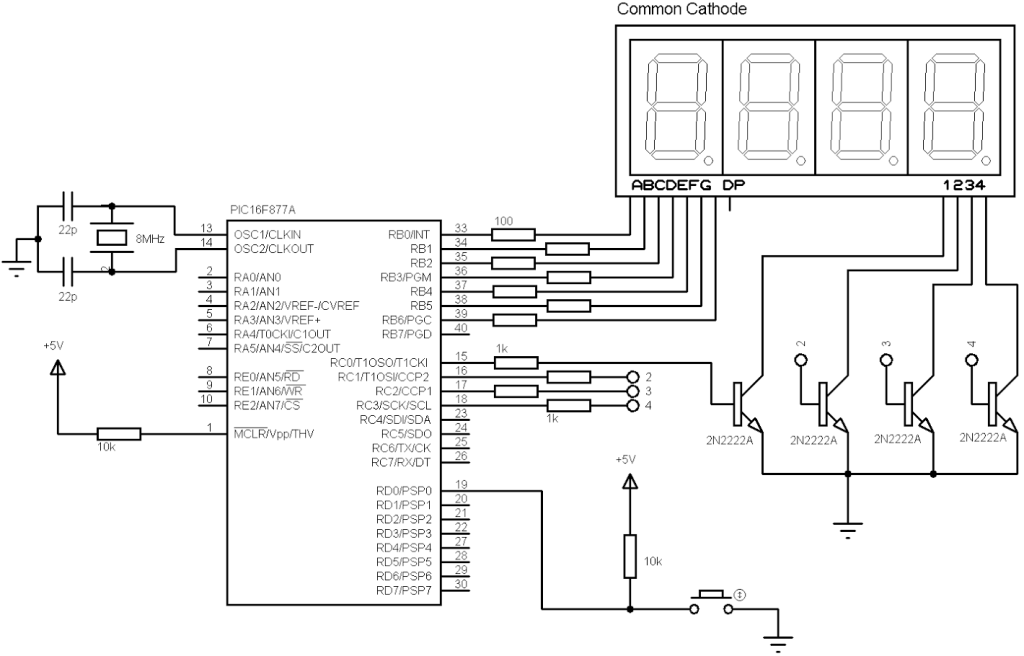
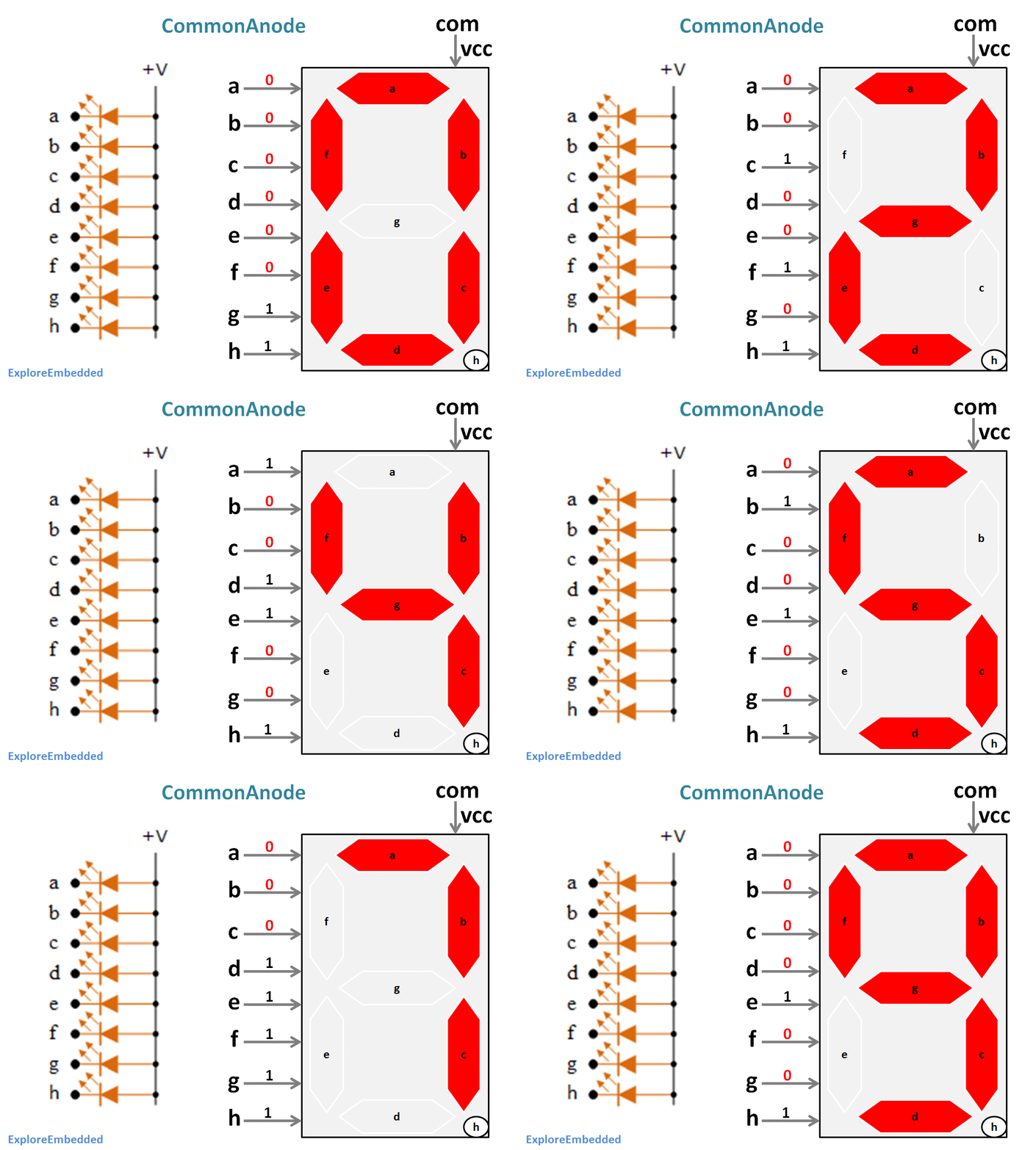
To drive a common-cathode display (Figure 8), the driver must have an active-high output. As indicated in the schematic in Fig.2.11, the seven segments (common anode) are connected to pins on the Cyclone IV. In this simple circuit, each anode terminal of the common cathode LED display is connected directly to the 4511 decoder/driver via a current limiting resistor. Next add a 330 Ohm resistor between each of the other connections to the Arduino. To drive a common-anode display (Figure 7), the driver must have an active-low output, in which each segment-driving output is normally high, but goes low to turn a segment on. It is better to directly connect pins 3 & 8 of the display to ground rail. Note that pins 3 and 8 of the display is the cathode terminals. For testing purpose only one 330 Ohm resistor (R2) is added between ground rail (0V) and the common cathode pins (3 & 8). Details of a common cathode type 7 segment LED display is shown here. Push Switch (S1) input point is at pin 9 of the Arduino.Ĭonnecting the display pins directly to Arduino I/O pins is not a good practice. To build this circuit youll need: A 4511 chip, such as the CD4511BE A 7-segment display (Must be common cathode. Just follow the schematic circuit diagram to make the entire project.Īrduino pins 2, 3, 4, 5, 6, 7 and 8 should go to Display pins 7, 6, 4, 2, 1, 9 and 10 in correct order. By Philip Kane This is s a quick introduction to the basics of using seven segment LED displays with microcontrollers. It is a combination of 8 LEDs (the decimal point -DP- is the 8th), which can be arranged so that different combinations can be used to make numerical digits.ĭetails of a common cathode type 7 segment LED display is shown here. The seven segment display is infact a very simple device. The whole circuit can be powered from a standard 9V PP3/6F22 battery, or from any suitable Arduino power adaptor. All the positive terminals are left alone.
#Common cathode 7 segment display circuit diagram code
The code (Arduino sketch) allows push button increment of the counter from 0 to 9. There are basically 2 types of seven-segment LED displays: Common Anode and Common Cathode 7 Segment LED Display Common Anode 7-Segment Display: All the Negative terminals (Anode) of all the 8 LEDs are connected together. 2 Digit Common Cathode 0.This is a simple 0 to 9 counter circuit constructed using Arduino! Here, a common cathode 7-segment LED display is connected to Arduino for displaying the digits.4 Digit Common Cathode 0.5″ – 7 Segment Display Module (Multiplexed).Refer Arduino pin configuration vs display bellow: Upload the code to Arduino Uno, apply 0 to 5V to Analog Pin A0 to Measure the voltage.

#Common cathode 7 segment display circuit diagram series
The current limiting resistors connected in series between the microcontroller pina and segment LEDs are 330 each. The microcontroller I/O pins source the current required for the segment LEDs.

#Common cathode 7 segment display circuit diagram how to
How To Control A 4 Digit 7 Segment Led Display With Max7219 Chip. The circuit diagram for connecting a common cathode seven segment LED display to the PIC16F688 microcontroller port is shown below. Working With Seven Segment Displays Introduction To The Basics. The user will be able to create a 0 to 5V DC Voltmeter using this code. 0 56 Inch 4 Digit Common Anode 7 Segment Display Clock Search Easyeda. The circuit diagram shows how a 4026 IC could be used to drive a common. Multiplexed Display InfoĪrduino code is provided to test the board. Seven - Segment Displays Seven - segment LED displays consist of seven small. A header connector is provided for easy interface to Arduino or other microcontrollers. The project works with 5V TTL signals but can be optimized for 3.3V operations by reducing the current limiting resistors’ value. This is a 3 Digit 7-segment display project that contains 3 x Common Cathode displays, current limiting resistors or each LED segment, 3 x PNP Transistor on each common cathode for multiplexing etc.


 0 kommentar(er)
